Pages

Saturday, December 1, 2012

My First Arduino Sketch

My Seeed Studio - Seeeduino V3.0 (Atmega 328P) Duemilanove compliant board and modules arrived at my home in upstate New York 5 days after I ordered it from the company in China. There are U.S. distributers, but after I added up all the costs and shipping, it was slightly less expensive to order directly from the company.

The board fired up and started the blink sketch as soon as I plugged it into my USB connector. Using both the Arduino IDE and VS2010 with the Arduino VisualMicro plugin, the board was easy to program. I would even say trivial. I don't have experience with other Arduino boards but this one easily re-loads a sketch without physically rebooting the board before download. It's auto-magic.

For my first project I connected (from left to right) a red led, slide switch, vibrator, passive infrared (PIR) and white LED modules into the Arduino Grove base shield. The white LED indicates the PIR sensor status and the vibrator module, if enabled, buzzes once when movement is sensed. I added the switch to enable or disable the vibrator module because my cats were circling the vibrating prey ready to slap the snot out of it if it buzzed just one more time. The red LED indicates if the vibrator module (cat warning) is activated.
I used the code samples from Seeed Studio (many thanks) for each of these modules to create the application, only changing the port assignments as needed.

const uint8_t    pirPin        =    2;  // PIR sensor
const uint8_t    ledPin        =    4;  // White LED
const uint8_t    vibPin        =    6;  // vibration module
const uint8_t    onOffPin      =    8;  // slide switch
const uint8_t    redLedPin     =    10; // red LED

void setup()
{
    pinMode(pirPin, INPUT );   // receive signal from PIR module
    pinMode(onOffPin, INPUT ); // switch enables vibrate module
    pinMode(ledPin, OUTPUT);   // light when motion detected
    pinMode(vibPin, OUTPUT);   // vibrate when motion detected
    pinMode(redLedPin, OUTPUT);// light when vibrator enabled

    Flash(5);
}

void loop()
{
    int pirValue    = digitalRead(pirPin);
    int onOffValue  = digitalRead(onOffPin);

    digitalWrite(redLedPin,onOffValue);

    bool vibrate = false;

    if( pirValue == 1 )
        digitalWrite(ledPin,HIGH);
    else
        digitalWrite(ledPin,LOW);

    if(IsEdgeGoingTrue(pirValue) && onOffValue > 0)
    {
        digitalWrite(vibPin,HIGH);
        delay(200);
        digitalWrite(vibPin,LOW);
    }
    delay(250);
}

void Flash( int times )
{
    for(int i=0; i<times; i++)
    {
        digitalWrite(ledPin, HIGH);
        delay(100);
        digitalWrite(ledPin, LOW);
        delay(100);
    }
        digitalWrite(vibPin,HIGH);
        delay(500);
        digitalWrite(vibPin,LOW);
}


// return true if state of signal goes from low to high
bool IsEdgeGoingTrue(bool signal)
{
    static bool lastState = false; // init once
    bool retval = false;

    if(!lastState && signal)
        retval    = true;

    lastState    = signal;

    return retval;
}


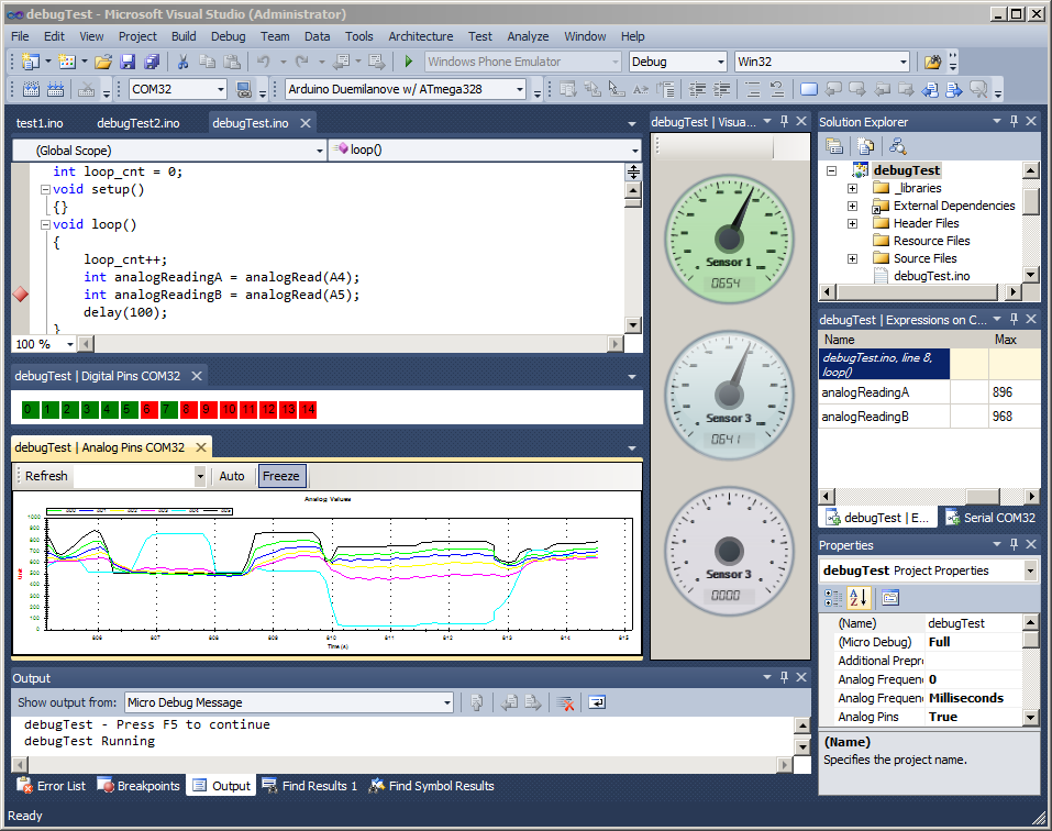
What is cool is that I ran this application, oops sketch, in Visual Studio with pin debug view on.


 It is my first priority to eliminate the loop() as I believe polling is not the best solution for any application, even trivial toys. My plan is to move my applications to an event driven state machine. I currently have a self made minimized version of Arduino Quantum Leaps QP in evaluation and hope that it is a viable event driven model that I can use rather than a high current "loop forever mostly doing nothing at all" solution. More on that soon.

... and Mr. Spanky has his eye on the offending vibrator module.


Monday, November 26, 2012

The VisualMicro Debugger plug-in upgrade

The VisualMicro Debugger Upgrade option to their Arduino plug-in is excellent! I've only begun to use it but it was easy to setup and get running after viewing the YouTube tutorial and reading some of their documentation. What will really help is the ability to record analog and digital responses without adding code to record it. For example, if you have a temperature module plugged into one of the analog ports, you can watch that port and see what values are being returned.

I highly recommend this plugin with the debugger upgrade.

I hope to include my own examples as my project develops.To get the upgrade you have to ask for a beta license. This free license will be available through January 2013. See their forum for more information.

Sunday, November 25, 2012

Arduino Software Development using VS2010

For software development I've decided to use VisualMicro, Arduino for visual studio. As a plugin, it integrates well with the Microsoft Visual Studio environment. This choice was based on the fact that I am familiar with the Microsoft Visual Studio tools, and they have a debugger available. I also downloaded and used the "standard" Arduino IDE, but I found it lacks a rich and robust UI.

The plug-in installation was not exactly straight forward and creating a project took some trial and error. When creating a project, and subsequent solution, the c++ style arduino sketch files were not recognized and would not compile. The instructions have you make the following c++ associations:

This indicates that these files will be associated with c++ projects. The problem I found (in my installation?) is that by creating a raw Arduino project (and subsequent solution) creates what appears to be c++ project, but most of the time (always?) main can't find the setup() and loop() functions that are defined in the .ino file even though it is associated correctly.

My workaround is to create a C++ project/solution first. Then I simply delete the c++ project and add a new Arduino (c++) project to the solution.


This works every time, although it is a little cumbersome. There is a possibility I have some setting(s) wrong, but if you read through the "test installation" directions there are some even more convoluted ways to setup an Arduino project.

January 2013 Update: I discovered that I can't (shouldn't?) use and dashes (and perhaps underscores) in the project name. Although I don't get a file naming error, the compile may indicate that main can't find setup() and loop().


Saturday, November 24, 2012

TinyDuino - Another tiny arduino kickstarter

Another Tiny Arduino project on Kickstarter just came to my attention. TinyDuino appears to be fully funded and has now entered stretch goals. It doesn't have as many shields, but is a tiny stackable micro-controller.

An entire stack of low power shields could be powered by a simple 3.3v button battery. This is a very clever idea with an extremely small profile. They are planning round form factors and lily pads as well.

I understand the processor is an Atmel ATmega328P, and an FTDI shield would snap onto that for programming. I like the fact that the FTDI USB interface chip could be removed after the micro is programmed. There are similar systems, but none that I know of just use a snap on connector.

The processor board and shields will be made in Ohio, with the board reported to be about $22 USD.

Monday, November 12, 2012

Standing Close to the Event Horizon

At this point in my micro controller adventure, I feel that I'm standing next to the event horizon of micro controller project development. By that I mean it would be easy to slip into low level ARM chip and coding; wire wrapping boards with tiny micro-controllers, or even worse. Right now the higher level boards have a USB connector that can power the board and download the program. However, this package can be reduced to just a board, but the underlying code and hardware will not have to be ported. For example, here is a compatible mini to the board I just ordered.


The dimensions of the Pro Mini PCB are approximately 0.7" x 1.3"

But is the future, there will emerge a new modular "Arduino" called smARtDUINO which at this time is in KickStarter here.

. .
It is a board level component system. In the above demonstration a quad core Arduino is built.


Arduino Prototyping, a beginner's thoughts

After eliminating the Netduino, I've chosen the Arduino platform for my prototyping. Here is the form factor for the Arduino Uno board. As you can see, for the most part the connectors expose the micro controller's i/o pins.
 
Arduino prototyping can be accomplished at the component level, and/or at a subsystem level. By component I mean a simple potentiometer or LED, and by subsystem I mean an entire assembly that does wireless networking for example. These higher level sub-assemblies are most often referred to as Arduino shields. These plug directly into and on top of the Arduino board, and then expose the pins for another shield or component. For example, here is the WiFi Shield:
Note that some shields are not complex subsystems but rather bus or pin extensions. I'm not going to discuss higher level shields at this point because I don't think I need them right now.

Prototyping can be accomplished by either a bread board of jumpered components, or with some inexpensive plugin modules similar in concept to Gadgeteer or GoBus, or probably a combination of both.

I originally started down the path of breadboards and components but discovered a module based component system from SeeedStudio called Grove that will help me prototype. The plugin components are called twigs, and they plug into a SeeedStudio Grove base board shown here:
This board plugs directly into the Arduino form factor and does little more than expose the analog (left side ports) and the digital i/o (center ports). Then by using a 4 wire connector, an inexpensive (compared to Gadgeteer or GoBus) component can be plugged into the board such as this Grove touch sensor and LED connected to some digital ports:

What could be simpler? As an added bonus, the built in micro controller I2C bus and SPI bus are exposed as a connector, but more on that later.

So my first order was a SeeedStudio version of the Arduino Duemilanove called Seeeduino V3.0 (Atmega 328P). As of this date it is in transit.
In addition to being one of the most inexpensive boards in its class, I also chose it because it is designed to run in either a 5 volt or 3.3 volt mode via a voltage select switch. The Atmega 328P chip is rated from 1.8v to 5.5 volts. This may be particularly useful if I can run my project on 4 AA rechargeable batteries for a reliable total of about 4.6 volts. Running at 5v requires a minimum of 7 volts in, which means 6 AA's at 1.2 volts for a solid 7.2 volts. In one forum I was told that most batteries only output about 1.2 to 1.3 volts throughout their life.

Netduino Wrap-up

In the previous three posts I outlined the three .Net Micro Framework platforms that can run code generated on a subset of the C# programming language; the GHI FEZ (Fast and EaZy) with Gadgeteer modules, Secret Labs LLC Netduino Go with GoBus modules and Netduino with Arduino shields. Each one of these platforms have their pros and cons and which one chosen would depend on the situation. Gadgeteer is very user friendly when you consider that it has a visual hardware connection screen in the IDE which automatically will help you select ports on the main board. GoBus has a lot of expansion capabilities and ability to run Gadgeteer S U and X modules. Lastly the Netduino board in an Arduino form factor opens up a lot shields and other components that have been around for a long time but it would be a bit harder to program than say a Gadgeteer, so each option has its advantages and disadvantages.

Of course the caveat here is that I do not actually own any of these boards, nor have I ever used them. My comments are only based on what I've read. These ramblings should at least give the casual hobbyist an idea for further reading. Also note there are differences in hardware and CPU capabilities that you might want to explore as well.